


Published on Apr 02, 2024
VALVE TIMING (VT) is one of the most important aspects of consideration in the design of an automobile engine. Simply defined, it is the timing, or regulation of the opening and closing of the valves. In simpler terms, it is the way an engine 'breathes'.
In an I.C.engine, usually the inlet valves open a few degrees (of crank angle) prior to TDC, and close after BDC. Similarly, the exhaust valves open a few degrees before BDC and close a few degrees after TDC. This is done to maximise:
" Intake of air/air-fuel mixture; and
" Scavenging, i.e. the exhaust of burnt gases.
Until recently, most engines around the world utilised ordinary or static VT, where the parameters of valve opening, lift, and closing (VO, VL and VC) were fixed. This was satisfactory at normal engine speeds, but posed problems at high and low speeds. Since the VT did not vary with speed, the additional requirements that arose at the extreme speeds could not be met with static VT. For example, at high speeds, the engine requires greater amounts of air. This implies that the IV should remain open for a longer period of time. This, though beneficial at high speeds, would be a menace at low speeds as it may lead to exhaust of unburnt fuel, which results in fuel wastage, increased emissions and lower performance.
This is where variable valve timing (VVT) comes into play. As the name suggests, the timing of the valves is not fixed, but varies, as per the demands of the situations. Therefore, the extra demands of the engine can be met, which in turn, results in improved engine performance.
Valve timing is the regulation of the points in the combustion cycle, at which the valves are set to open and close. Since the valves require a finite period of time in which to open or close without abruptness, a slight lead-time is always necessary for proper operation. The design of the valve-operating cam provides for the smooth transition from one position to the other, while the cam setting determines the timing of the valve.
In a typical four-stroke engine, the inlet valve is set to open before TDC (top dead centre), towards the end of the exhaust stroke and close after BDC (bottom dead centre), at the start of the compression stroke.
While the intake valve should open, theoretically at TDC, most engines utilise an intake valve opening, which is timed to occur a few degrees prior to the arrival of the piston at TDC on the exhaust stroke. This is because by the time the valve becomes fully open, the piston would have travelled considerably down the bore, and since the valve would have to be fully closed before BDC, the actual time the valve would be fully open would be minimal.
Additionally, the inertia of the incoming mixture plays a big role. Keeping the inlet valve open after BDC forces more mixture to pack into the cylinder, in spite of the fact that the piston is moving upwards.
The exhaust valve is set to open before BDC, towards the end of the power stroke and close after TDC, at the beginning of the intake stroke. The reason the exhaust valve is opened before BDC is to prevent the exhaust gases from forming a high-pressure cushion, which would impede the movement of the piston and rob the engine of power. This also ensures that the valve is fully open at the start of the exhaust stroke. Keeping the exhaust valve open after TDC ensures that the entire burnt mixture is thoroughly scavenged.
Valve overlap refers to the time when both the intake and exhaust valves are open. It ensures that the exhaust gases rushing out of the cylinder create suction, in order to draw in fresh mixture, and the fresh mixture entering the cylinder pushes out the burnt fuel mixture.
Therefore, valve timing of any engine depends on:
" The amount of valve overlap
" Lag and lead, i.e. the degrees that the crankshaft turns between valve opening and TDC or BDC
" The intended usage of the engine.
With VVT, a sensor is used to detect the engine's speed. An electronic system then uses this information to adjust the valve opening and closing timings accordingly. This avoids the problems associated with static valve timing, and also allows for maximum torque at all engine speeds.
Cam-phasing VVT is at present, the simplest, cheapest and most commonly used mechanism. However, its performance gain is also the least. Basically, shifting the phase angle of camshafts varies the valve timing. For example, at high speeds, the inlet camshaft will be rotated in advance by 30° so as to enable earlier intake. This movement is controlled by an engine management system according to need, and actuated by hydraulic valve gears.
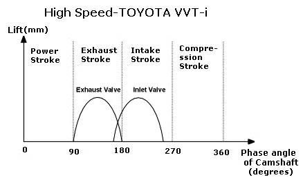
Fig 3-1: Lift v angle diagram (Toyota VVT-i)
Cam-phasing VVT cannot vary the duration of valve opening. It only allows earlier or later valve opening. Earlier opening results in earlier close. It cannot vary the valve lift. However, cam-phasing VVT is the simplest and cheapest form of VVT because each camshaft needs only one hydraulic phasing actuator, unlike other systems that employ individual mechanism for every cylinder.
Better systems have continuous variable shifting, say, any arbitrary value between 0° and 30°, depending on r.p.m. This provides the most suitable valve timing at any speed, thus greatly enhancing engine flexibility. Moreover, the transition is so smooth that it is hardly noticeable.
The end of camshaft incorporates a gear thread. The thread is coupled by a cap, which can move towards and away from the camshaft. Because the gear thread is not in parallel to the axis of camshaft, phase angle will shift forward if the cap is pushed towards the camshaft. Similarly, pulling the cap away from the camshaft results in shifting the phase angle backward. The hydraulic pressure determines push or pull. There are two chambers right beside the cap and they are filled with liquid. A thin piston separates these two chambers, the former attaches rigidly to the cap.
Liquid enter the chambers via electromagnetic valves, which controls the hydraulic pressure acting on which chambers. For instance, if the engine management system signals the valve at the green chamber open, then hydraulic pressure acts on the thin piston and push the latter, accompany with the cap, towards the camshaft, thus shift the phase angle forward. Continuous variation in timing is easily implemented by positioning the cap at a suitable distance according to engine speed.
Advantages: Cheap and simple; continuous VVT improves torque delivery across the whole rev (speed) range.
Disadvantages: Lack of variable lift and variable valve opening duration, thus it produces less top end power.
Applications: Most car makers, such as:
Audi 2.0-litre - continuous inlet
Audi V8 - inlet, 2-stage discrete
BMW Double Vanos - inlet and exhaust, continuous
Ferrari 360 Modena - exhaust, 2-stage discrete
Fiat (Alfa) SUPER FIRE - inlet, 2-stage discrete
Ford Puma 1.7 Zetec SE - inlet, 2-stage discrete
Ford Falcon XR6's VCT - inlet, 2-stage discrete
Jaguar AJ-V6 and updated AJ-V8 - inlet, continuous
Lamborghini Diablo V12 since SV - inlet, 2-stage discrete
Mercedes V6 and V8 - inlet, 2-stage
Nissan VQ V6 - inlet, continuous
Nissan VQ V6 since Skyline V35 - inlet, electromagnetic
Porsche Variocam - inlet, 3-stage discrete
Toyota VVT-i - continuous, mostly inlet but some also exhaust
Volvo 4 / 5 / 6-cylinder modular engines - inlet, continuous
Volkswagen VR6 - inlet, continuous
Honda pioneered road car-used VVT in the late 80s by launching its famous VTEC system (Valve Timing Electronic Control). First appeared in Civic, CRX and NS-X, and then became standard in most models.
Two sets of cams having different shapes to enable different timing and lift. One set operates during normal speed, say, below 4,500 r.p.m.. The other set substitutes at higher speeds. Such layout does not allow continuous change of timing, therefore the engine performs modestly below 4,500 r.p.m. but above that it will suddenly transform into a wild animal.
This system does improve peak power - it can raise red line to nearly 8,000 r.p.m. (even 9,000 r.p.m. in S2000), just like an engine with racing camshafts, and increase top end power by as much as 30 hp for a 1.6-litre engine. However, to exploit such power gain, the engine must be kept boiling at above the threshold r.p.m., therefore frequent gear change is required. As low-speed torque gains too little (remember, the cams of a normal engine usually serves across 0-6,000 r.p.m., while the "slow cams" of VTEC engine still need to serve across 0-4,500 r.p.m.), drivability won't be too impressive. In short, cam-changing system is best suited to sports cars.
Advantages: Powerful at top end
Disadvantages: only 2 or 3 stages; non-continuous; only slight improvement in torque; complex structure
Applications:
Honda VTEC,
Mitsubishi MIVEC,
Nissan Neo VVL.
Toyota originally introduced the VVT-i (Variable Valve Timing - intelligent) as a revolutionary design that increases engine torque and output while addressing environmental issues. By adjusting the intake valve opening timing according to the engine speed, more oxygen is supplied through the air intake valve as more fuel is injected into the combustion chamber. Power and torque is maximized due to larger scale combustion. This optimised fuel to air ratio ensures the air-fuel mixture is combusted more thoroughly.
The VVT-i portion of the system continuously varies intake valve timing throughout the rev range by hydraulically rotating the camshaft relative to its drive gear. Note that VVT (without the "i") did not do this continuously. The VVL portion of the system incorporates two distinct cam profiles. However, the actual mechanism is quite different. Both cam lobes operate a single, wide rocker arm that acts on both intake or both exhaust valves. A needle-bearing roller on the arm follows the low-r.p.m., short-duration, low-lift lobe, forcing both valves to open and close on that profile.
The roller design and roller bearings on the rocker arm pivot help to minimize valve train friction. The high-r.p.m., higher-duration, longer-lift lobe rubs on a hardened steel slipper follower mounted to the rocker arm with a spring. Even though the high-r.p.m. lobe is pushing down further than the low-r.p.m. lobe, the spring absorbs the extra movement. At 6000 r. p.m., the ECU sends a signal to an oil control valve at the end of the camshaft that puts oil pressure behind a lock pin in the rocker arm, sliding the pin under the spring-loaded slipper follower, locking it to the rocker arm and forcing the arm to follow the high-r.p.m. cam profile.
Combining cam-changing VVT and cam-phasing VVT could satisfy the requirement of both top-end power and flexibility throughout the whole rev range, but it is inevitably more complex. Presently, only Toyota and Porsche have such designs. However more and more sports cars are believed to adopt this VVT mechanism in the future.
The VVTL-i system comprises four major components:
1. The Electronic Control Unit (ECU), which calculates optimum intake valve timing and decides whether or not to operate the cam changeover mechanism based on engine operating conditions.
2. The Oil Control Valve (OCV) for variable valve timing, which controls hydraulic pressure, and in turn the VVT Pulley, under instruction from the ECU.
3. The Oil Control Valve (OCV) for variable valve timing and lift, which controls hydraulic pressure to operate the cam changeover mechanism.
4. The VVT Pulley, which continuously changes the intake valve timing using hydraulic pressure.
Toyota’s VVTL-i is the most sophisticated VVT design yet. Its powerful functions include:
Continuous cam-phasing variable valve timing
2-stage variable valve lift plus valve-opening duration
Applied to both intake and exhaust valves
The system could be seen as a combination of the existing VVT-i and Honda’s VTEC, although the mechanism for the variable lift is different from Honda.
| Are you interested in this topic.Then mail to us immediately to get the full report.
email :- contactv2@gmail.com |
